QFCI-I/O/RM-JM
Download Datasheet PDF QFCI-I/O/RM-JM Armoured SHF1 or SHF2 Indoor and outdoor, loose tube 4, 8 , 12, 24 or 48... read more
Description
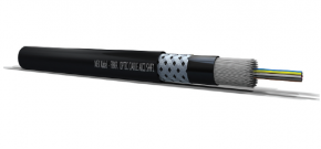
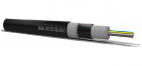
QFCI-I/O/RM-JM
Armoured SHF1 or SHF2 Indoor and outdoor, loose tube
4, 8 , 12, 24 or 48 fibers
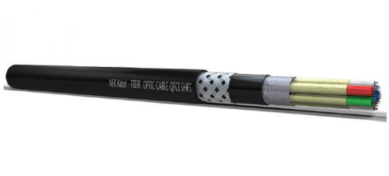
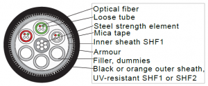
| Application: Optical cable for indoor and outdoor use in vital communication and emergency systems that need to be operational during fire. The cable is designed to ensure operation for more than 3 hours in fires up to 1000ºC. The cable is halogen free and flame retardant to protect against secondary damage to electronic equipment during and after fire. Outer sheath is made from black or orange UV- stabilized and weather resistant material and may be exposed for shorter periods to fluids such as diesel, petrol, glycol, ethanol, white sprite and ASTM oil 2. The resistance to these fluids is according to DOD-STD-1678, method 8030.The cable is reinforced with a steel wire braiding. The fibres are protected in jelly filled loose tubes stranded around a central strength member to ensure optimum performance and long life. Each fiber and loose tube is color coded for easy identification during splicing and termination. The outer sheath is marked to show fibre type and cable type. |
||||||||||
| Specifications: Temperature installed: -40 to +70 [°C] Temperature @ installation: -10 to +60 [°C] Tensile installed (IEC 60794-1-2E1): 500 [N] Tensile @ installation: 1500 [N] Crush (IEC 60794-1-2E3): 3000 [N/10cm] Impact (IEC 60794-1-2E4): 30 [J] Torsion (IEC 60794-1-2E7): ±1 [turn/m] Min.bending diam. fixed: 15 x outer diam Min.bending diam. flexible: 20 x outer diam Norms SHF1 and SHF2: Chemical resistance: IEC 60811-2-1 (Mineral oils) Fire and smoke: IEC 60331-25, BP-236, IEC 61034 IEC 60332-3 catA and C, IEC 60754-1, IEC 60754/2 |
| Norms SHF2 only: Oil reistant: IRM 902 (IEC 60811-404) Ozone resistant: IRV 902 (IEC 60811-403) |
||||||||||||||
| Approval: DNV CERTIFICATE NO. E-11775 | ||||||||||||||
| Date Rev. | ||||||||||||||
| 16.03.2015 1 Armour | ||||||||||||||
| Multimode fibres | MM 62.5 IEC 60793-2-10 Type A1b Telecordia GR-20-core |
MM 62.5 OM1+ HiCap |
MM50 ITU-T G651.1 IEC 60793-2-10 Type A1a.1 Telecordia GR-20-core |
MM50-OM3 ISO/IEC 11801 IEC 60793-2-10 Type A1a.2 Telecordia GR-20-core |
MM50-OM4 ISO/IEC 11801 IEC 60793-2-10 Type A1a.2 Telecordia GR-20-core |
|||||||||
| ITU-T type | – | – | G 651 | – | ||||||||||
| Core Diameter | mm | 62.5 ± 2 | 62.5 ± 2 | 50 ± 2 | 50 ± 2 | 50 ± 2 | ||||||||
| Core non-circularity | % | <_ 5 | <_ 5 | <_ 5 | <_ 5 | <_ 5 | ||||||||
| Cladding Diameter | mm | 125 ± 1,0 | 125 ± 1,0 | 125 ± 1,0 | 125 ± 1,0 | 125 ± 1,0 | ||||||||
| Coating Diameter | mm | 245 ± 5 | 245 ± 5 | 242 ± 5 | 242 ± 5 | 242 ± 5 | ||||||||
| Cladding non-circularity | % | 0,7 | 0,7 | 0,7 | 0,7 | 0,7 | ||||||||
| Core/cladding concentricity error | mm | <_ 1,0 | <_ 1,0 | <_ 1,0 | <_ 1,0 | <_ 1,0 | ||||||||
| Coating/cladding concentricity error | mm | <_ 10 | <_ 10 | <_ 6 | <_ 6 | <_ 6 | ||||||||
| Numerical Aperture | mm | 0.275 ± 0.015 | 0.275 ± 0.015 | 0.200 ± 0.015 | 0.200 ± 0.015 | 0.200 ± 0.015 | ||||||||
| Proorf test | kpsi | >_ 100 | >_ 100 | >_ 100 | >_ 100 | >_ 100 | ||||||||
| Attenuation Bandwith |
at 850 nm | db/km (max) | <_ 3,5 | <_ 2,8 | <_ 2,8 | <_ 2,8 | <_ 2,8 | |||||||
| at 1300 nm | db/km (max) | <_ 1,0 | <_ 0,7 | <_ 0,8 | <_ 0,8 | <_ 0,8 | ||||||||
| at 850 nm | MHz x km | >_ 200 | >_ 250 | >_ 500 | >_ 1500 | >_ 3500 | ||||||||
| at 1300 nm | MHz x km | >_ 500 | >_ 1000 | >_ 500 | >_ 500 | >_ 500 | ||||||||
| 1 G BASE Ethernet | SX 850 nm | m | 275 | 500 | 600 | 1000 | 1100 | |||||||
| 1 G BASE Ethernet | LX 1300 nm | m | 550 | 1000 | 550 | 550 | 600 | |||||||
| 1 G BASE | SR 850nm | m | 35 | 65 | 86 | 300 | 550 | |||||||
| 1 G BASE | LX4 1300 nm | m | 300 | 450 | 300 | 300 | 300 | |||||||
|
Single mode SMR 9/125/250 | Single mode SMR LWP 9/125/250 | Non-zero Dispersion | Single mode | ||||||||||
| ITU-T type | G652.B | G652.D | G655 | G654 | ||||||||||
| Mode Field diameter (MDF) |
at 1310 nm at 1550 nm |
mm mm |
9.2 ± 0.4 – |
9.2 ± 0.4 – |
– 9.2 ± 0.5 |
– 12 ± 0.5 |
||||||||
| Cladding Diameter | mm | 125 ± 1 | 125 ± 0.7 | 125 ± 1 | 125 ± 1 | |||||||||
| Coating Diameter | mm | 245 ± 10 | 245 ± 5 | 245 ± 10 | 245 ± 10 | |||||||||
| at 1310 nm | db/km (max) | <_ 0.38 | <_ 0.35 | – | – | |||||||||
| Attenuation | at 1383 nm at 1550 nm |
db/km (max) db/km (max) |
– <_ 0.25 |
<_ 0.33 <_ 0.25 |
– <_ 0.25 |
– <_ 0.19 |
||||||||
| at 1625 nm | db/km (max) | – | <_ 0.28 | <_ 0.28 | <_ 0.21 | |||||||||
| Zero dispersion wavelength | l0 | 1302 – 1322 | 1302 – 1322 | – | – | |||||||||
| Chromatic Disper- sion |
at 1285 – 1330nm |
ps/nm x km | <_ 0.35 | <_ 0.35 | – | – | ||||||||
| at 1550 nm | ps/nm x km | <_ 18.0 | <_ 18.0 | – | – | |||||||||
| at 1530 – 1565 nm |
ps/nm x km | – | – | 5.5 to 10.0 | 22 | |||||||||
| at 1565 – 1625 nm |
ps/nm x km | – | – | 7.5 to 13.0 | – | |||||||||
| PDM | at 1550 nm | ps/vkm | – | – | <_ 0.20 | <_ 0.20 | ||||||||
| 1 G BASE Ethernet | SX 1310 nm | m | 10000 | 10000 | ||||||||||
| 1 G BASE Ethernet | LX 1550 nm | m | 40000 | 40000 | ||||||||||
| 1 G BASE | SR 1310nm | m | 10000 | 10000 | ||||||||||
| 1 G BASE | LX 1550 nm | m | 40000 | 40000 | ||||||||||

